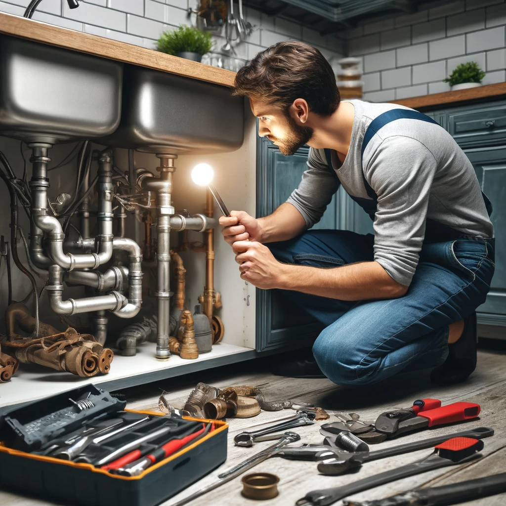
A bypass is quite simple to explain: it’s a section of a water supply or heating system pipeline installed at key points along the circuit. This simple engineering solution simplifies repair and maintenance of pipeline fittings and pumps, improves efficiency, and improves heating quality. A bypass allows you to shut off a system component, or rather, bypass the flow of coolant.
Bypass device
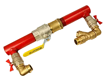
A bypass, also known as a bypass pipe, is a pipeline used to redirect the flow of the working fluid around a specific point in the heating system, such as a radiator, pump, branch pipe, etc. The bypass pipe is connected at one end to the inlet pipe of the circuit and at the other to the outlet pipe. Shut-off valves (such as a tap, valve, or gate valve) are installed upstream of the bypass inlet. The flow of the working fluid is either completely shut off or the amount supplied to the device is regulated.
Bypass pipes were initially used to perform repairs or maintenance on pipeline mains without completely shutting down the system. This simple solution later became a requirement for installing one-pipe systems and became known as a bypass. In two-pipe systems, the device is completely unnecessary.
What types of bypasses are there?
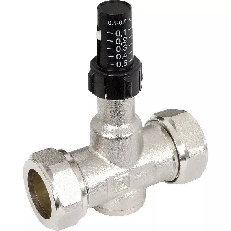
Shut-off valves are installed not only after the inlet or before the outlet of a bypass, but also on it. Based on this feature, and depending on the type of shut-off mechanism, bypasses are divided into three types:
- Mechanically (manually) controlled.
- Static (non-adjustable).
- Automatic
Each type has its own design features and usage methods.
In vertical piping systems, bypass structures consist of connected pipes with tees that distribute the flow among multiple heating radiators.
Non-adjustable bypass
If there are no shut-off valves on the bypass pipe or upstream of the heating appliance’s inlet pipe, then the bypass is uncontrolled. In such cases, the pipeline design is simplified, but allows for the future installation of additional heating appliances. Once they are installed, the bypasses will be activated. When designing new pipeline systems, it is assumed that there are no control shut-off valves, and calculations are made only assuming free flow of the working fluid without hydraulic forces.

During further operation, adjustments are made to the calculations. Depending on the intended use of a particular section, permissible hydraulic pressure values are established in the static bypass diagrams. Equipment with the required characteristics is selected in accordance with the calculation data.
The cross-sectional area of the vertical bypass pipe is always smaller than the internal diameter of the main main branches. This is necessary to ensure that the free flow of coolant, under the force of gravity, does not completely drain into the nearby bypass pipe. If the diameters are identical, then most of the working fluid through the bypass pipe will not reach the heating device, but will circulate in front of it.
Other physical laws are used in horizontal heating system layouts. Here, calculations are based on the tendency of the hot medium to rise due to its lower specific gravity. The diameters of the bypass loops in the lower layouts should be the same as the cross-sections of the main pipes, while the diameters of the branches to the heating devices should be smaller. This increases the pressure in the regulated system elements, distributing the coolant more evenly throughout the circuit.
Manual bypass
Manual flow control through the bypass pipe is accomplished using ball valves. This shut-off mechanism design is used because the open flow passage of the valve creates no obstructions that could affect even minor fluctuations in hydraulic pressure. Additional hydraulic resistance negatively impacts the accuracy of temperature control. When the valve is fully closed, all coolant passes through the bypass. This is called the primary flow path of the working fluid through the system.
Note: The surfaces of the ball valve mechanisms tend to stick to each other if they are not used for a long time, so the valves should be turned periodically, even if not absolutely necessary.
Bypasses with manually adjustable valves are typically used in individual heating systems in private homes. Installing shutoff valves on bypass lines in multi-story residential buildings poses the risk of inadvertently shutting off water supply to adjacent consumers. Manually adjustable bypass valves are also used for hydraulic pump connections in single-pipe heating systems.
Automatic bypass
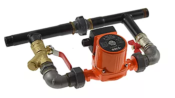
Bypass pipes with automatic valves are used to connect hydraulic pumps with free-flowing working fluids without pumping units. In these pumps, booster pumps can be installed as flow accelerators in multi-story buildings to reduce heat loss and increase efficiency for more uniform heating of the rooms.
With automatic flow control, flow redirection occurs based on the set temperature of the medium, without human intervention. When the pump is running, water flows only through it, and the electrical bypass is closed. If the pump stops working (due to a power outage or malfunction), the working fluid flows through the bypass pipe. The flow is partially or completely blocked by the immobilized blades of the pump.
Automatically controlled bypasses are divided into two types:
- Valve;
- Injection.
In automatic bypasses with valve-controlled fluid distribution, ball valves are installed in the bypass pipes. This reduces hydraulic resistance and ensures maximum free flow of the working fluid by gravity.
An operating pump increases pressure, which increases the speed of the coolant, which rushes back into the main line before it has time to cool. Then, with minimal temperature loss, it moves unimpeded through the circuit to fill other heating elements. To prevent backflow, check valves are used.
The check valve mechanism contains a steel ball that is pressed tightly against the seat of the control device during reverse flow, but leaves the flow opening open during forward flow.
When the pump is running, pressure is created, and the coolant presses the ball against the seat, closing the forward flow. When the pump is turned off, the coolant begins to flow through the bypass pipes. It should be noted that the valve bypasses
They are sensitive to media contamination (scale, rust, and scale flakes), so filters are required. The pipeline fittings include special cut-in sumps with replaceable filter elements and drain valves.
Injection bypasses operate similarly to a hydraulic elevator. A pump unit is inserted into the main water supply pipe so that the inlet and outlet pipes of the bypass continue within the main water supply pipe.
The pressure from the pump’s operation forces some of the fluid into the inlet pipe’s diffuser, accelerating its circulation through the unit. At the outlet pipe, the internal diameter narrows, forming a nozzle from which the coolant returns to the main pipe at an accelerated rate. The remaining working fluid is carried along with the pressure jet, transferring the kinetic energy of the pressure head to it. The entire flow in the main line accelerates, and the water in the main line continues to move, but at an accelerated rate. Reverse currents are not excluded in such cases. When the pump is off, the working fluid moves through the bypass unforced.
In heating mains with injection bypasses, the momentum for fluid movement is transferred from the pressure head. Here, too, shut-off equipment requires maintaining the cleanliness of the working fluid using filters.
Purpose of bypass sections
Bypass pipelines maintain coolant circulation in the event of a pump failure or during a power outage. Any heating element controlled by the bypass can be shut off or completely disconnected from the main line by diverting the flow through the bypass pipe by closing the valves on the inlet and outlet ports. This eliminates the need to shut down and completely drain the heating system during scheduled maintenance.
In individual heating systems in private homes, bypasses are used for:
- connecting additional radiators
- connecting circulation pumps
- connecting a distribution manifold when installing underfloor heating
- creating a small circuit in a solid fuel boiler heating system.
When connecting a circulation pump, the bypass pipe functions as the main pipeline. Therefore, shut-off valves are installed in the bypass pipe, not on the inlet or outlet ports. This installation method is the only way to prevent coolant recirculation.
Radiator piping
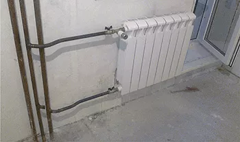
Bypass pipes are used exclusively in one-pipe systems, since in manifold and two-pipe systems, the radiator batteries are connected to the supply line in parallel, and the coolant flows to them at the same temperature. The operation of the entire system will not be affected by the malfunction of any one heating circuit if shut-off valves are installed.
In series-connected radiator batteries in a one-pipe system, the water cools faster as it passes through all circuits. The greater the radiator’s heat output, the colder the water will be at the outlet. However, if there are no bypasses in a one-pipe system, then the radiators closest to the main line will receive the maximum amount of heat.
The return and supply pipes, connected by a jumper, divide the flow of the working fluid into two parts: one part transfers heat to the room, while the other, maintaining its temperature, flows through a bypass pipe to the next radiator. With bypasses, the entire circuit of radiators will operate uniformly, maintaining the same temperature on both the radiator closest to the main line and the one furthest from it.
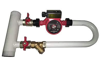
Bypass in the pump piping
Connecting circulation pumps to bypasses is practical in gravity-fed systems. The system requires a booster manifold, specific pipe diameters, and consistent slope angles. Pumps improve heating efficiency in northern regions, where ambient temperatures can drop below 30°C. However, it’s important to remember that forced-air heating systems will reduce heating efficiency to virtually zero if the pump fails or the centralized power supply is disconnected. To avoid heating problems in such cases, it’s best to consider an independent power supply system from the outset and install the pumps on the main line, not on bypasses.
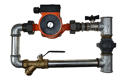
A pump connected to the bypass prevents backflow of the coolant and its movement in a closed loop, thus maintaining its high temperature. However, even if a pump is installed in the bypass, a check valve must be installed in it to prevent convective reverse flow of the working fluid. In an injection pump, reverse flow of the coolant is eliminated.
A hydraulic pump can be installed on the bypass yourself, but ready-made pump units are also available. Piping is arranged as space allows.
Bypass in underfloor heating systems

A bypass in an underfloor heating system is part of its mixing unit. The bypass pipe operates continuously, ensuring the proper functioning of the underfloor heating system.
If the coolant temperature in the supply pipe reaches 80°C, water is supplied to the floor circuit through the bypass at an operating temperature of 40-45°C. To ensure proper preparation of the underfloor heating fluid, a three-way valve is used in the mixing unit, allowing the required amount of heated water to flow. The remaining coolant passes through the bypass, mixes with cooled water from the manifold, and is sent through the main pipe to the boiler.
The function of the three-way valve is to meter the flow of the working medium for heating, and return the excess through the bypass into the main line.
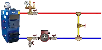
Bypass in a heating system with a solid fuel boiler
In this type of piping, the bypass plays a key role, creating a small circuit for the working fluid. One end of the bypass is connected to the supply pipe, the other to the three-way valve on the return pipe. Water returning from the heat-dissipating circuit mixes in the valve with hot water from the bypass. Therefore, the boiler receives liquid at a temperature of approximately 50°C.
This type of piping is essential for a solid fuel boiler, as cold water will cause condensation to form on its walls, which can lead to rapid corrosion and premature failure.
Conclusion
As we can see, a simple section of pipe can play a key role in the efficiency of heating systems. A bypass distributes the flow of the working fluid to ensure the required coolant temperature to all radiators, regardless of their location relative to the main line. Bypass pipes allow for servicing heating circuits and repairing their heating elements without shutting down the entire system.